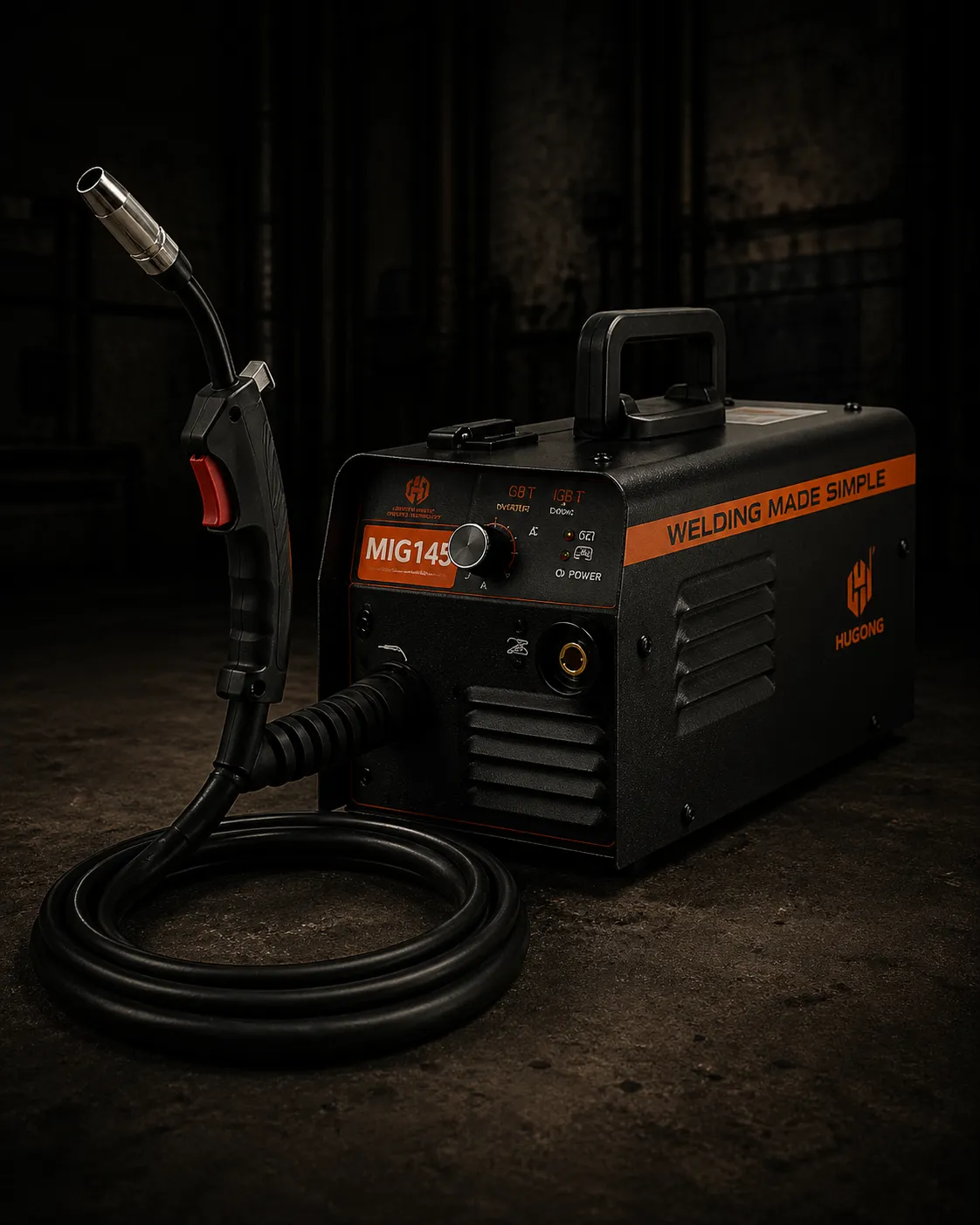
Industrial Welding Services Vasai - MIG, TIG, ARC & Spot Welding Job Work Vasai - Mumbai - Palghar
MIG - TIG - ARC - Spot Welding - MS / SS 304 / SS 316 / GI / Aluminium - 6 Machines - ISO 9001:2015
Aero Enterprises Unit I, Vasai Phata provides MIG, TIG, ARC, and resistance spot welding services in Vasai, Mumbai, and Palghar. We operate a 6-machine industrial welding division welding MS IS 2062, SS 304, SS 316, GI IS 277, aluminium, brass, and copper across structural weldments, precision thin-gauge assemblies, and high-volume spot-welded hardware. ISO 9001:2015 certified welding services with WPS-controlled joint procedures, pre-weld fixturing, dye penetrant testing on structural joints, and direct integration into fiber laser cutting, CNC press brake bending, and 7-tank powder coating on the same production floor at Unit I.
Expertise and Experience
Aero Enterprises Unit I Vasai Phata operates a 6-machine welding division comprising 4 multi-process inverter welding units capable of MIG, TIG, and ARC processes and 2 resistance spot welders. The division welds MS IS 2062, SS 304 and 316, GI IS 277, aluminium, brass, and copper across structural weldments, precision thin-gauge assemblies, modular fabrication, and high-volume spot-welded hardware. Welding at Unit I is an integrated production stage where laser-cut and press-brake-formed components are assembled and welded before entering the 7-tank powder coat pre-treatment line. Every structural weld joint is visually inspected and dye penetrant tested.
Why Our Process Wins
The most common welding failure mode is not the weld itself; it is the sequence and fixturing decision made before the first arc is struck. A component welded without adequate fixturing distorts during the weld thermal cycle. At Aero Enterprises Unit I, every welded assembly is fixtured before welding. Weld sequence is defined to minimise heat accumulation. On thin-gauge CR IS 513 below 1.5mm, stitch welding sequences with controlled inter-pass cooling are mandatory.
Machinery · Unit I Vasai Phata
4x Multi-Process Inverter Units, 2x Resistance Spot Welders. Integrated with Laser Cutting, Press Brake, and Powder Coat Line.
Core Capabilities
Verification Protocol
WPS review defined before the first arc is struck on any new component.
Pre-weld fixturing verification for dimensional alignment.
Visual inspection of weld bead profile, undercut, and spatter on all joints.
Dye Penetrant Testing (DPT) on structural and concealed joints.
Destructive peel test on spot weld batch samples.
Post-weld dimensional audit before finishing.
Stamping Operations
Six stamping and forming operations run simultaneously across the 20-press floor. Each has a correct application — specifying the wrong operation produces defects that cannot be corrected downstream.
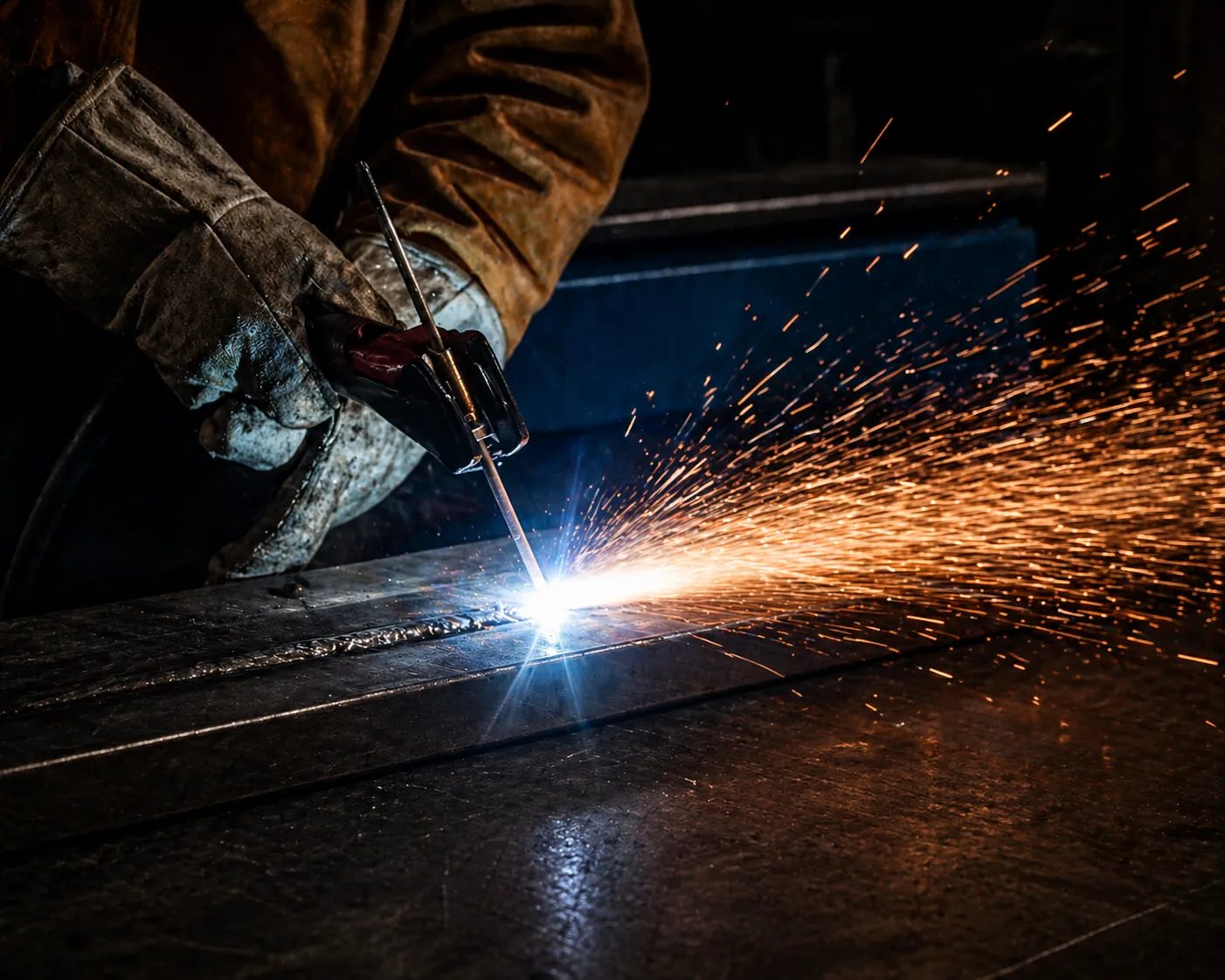
MIG Welding
MIG (Metal Inert Gas) welding feeds a continuous consumable wire electrode through the welding gun while shielding the weld pool with an inert or semi-inert gas — typically CO₂ or Argon/CO₂ mix. High deposition rate makes MIG the correct process for structural MS weldments, frame fabrication, and medium-to-heavy gauge bracket assemblies where throughput is priority. At Unit I, all 4 multi-process inverter machines run MIG for MS structural work.
Applications
MS IS 2062 structural frames · Enclosure assemblies · Bracket fabrication · GI IS 277 structural joints
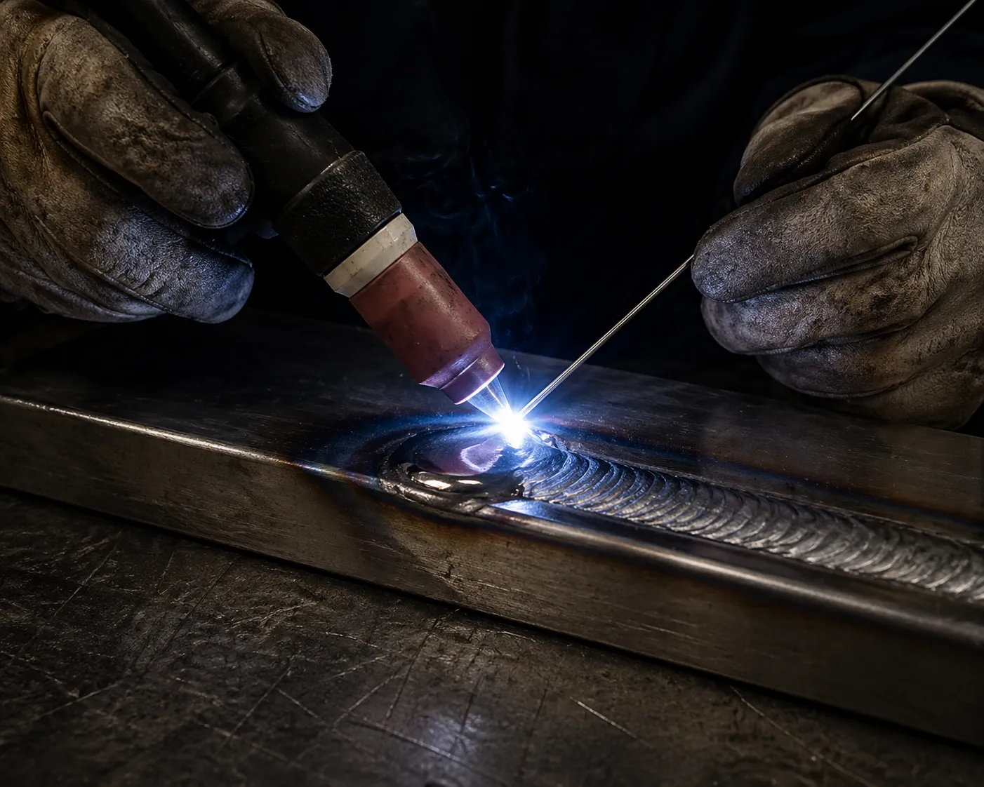
TIG Welding
TIG (Tungsten Inert Gas) welding uses a non-consumable tungsten electrode with separate filler wire addition, shielded by pure argon. TIG produces precise, low-heat-input welds with a cosmetically clean bead. It is the correct process for SS 304, SS 316, aluminium, thin-gauge material below 2mm, and any joint where heat-affected zone size and bead appearance are specification requirements. At Unit I, argon back purging is used on closed SS sections during TIG welding.
Applications
SS 304 / SS 316 · Aluminium · Brass · Copper · Thin gauge below 2mm · Cosmetic visible joints
ARC / Stick Welding
ARC (Stick) welding uses a flux-coated consumable electrode. The flux coating produces its own shielding gas on decomposition, making ARC independent of external gas supply. ARC is the correct process for thick-section MS above 6mm requiring high-penetration joints, for site and field repair work, and for joints with access constraints that prevent MIG wire feed. At Unit I, ARC is used for heavy structural MS above 6mm thickness.
Applications
MS IS 2062 above 6mm · Heavy structural joints · High-penetration fillet and butt welds
Resistance Spot Welding
Resistance spot welding passes high electrical current through two copper electrodes clamped on either side of the sheet metal stack, generating heat at the faying interface to form a weld nugget. No filler material, no shielding gas, no external heat source. The nugget diameter and penetration are controlled by electrode force, current, and weld time — all set on the machine controller. Correct for thin-gauge sheet metal assemblies, hardware joining, and high-volume panel fabrication where continuous seam welding is not required.
Applications
Thin-gauge MS and CR assemblies · Hardware panel joining · Modular enclosure panels · High-volume bracket assembly
Structural Weldment
Multi-component structural assemblies — frames, base structures, support weldments, and fabricated sub-assemblies — are produced at Unit I from laser-cut and press-formed blanks on the same floor. Every structural weldment uses a defined Welding Procedure Specification covering joint preparation, fillet size, weld sequence, and inter-pass temperature before the first arc is struck. WPS-controlled structural welding is what separates a dimensionally consistent weldment from a distorted one.
Applications
Structural frames · Solar tracker assemblies · Industrial base structures · Heavy fabricated sub-assemblies
Post-Weld Finishing
All welded assemblies at Unit I undergo post-weld spatter removal and toe dressing before powder coat application. Cosmetic-grade assemblies receive full weld bead grinding and polishing to produce a flush surface. GI IS 277 weld zones are treated with zinc-rich cold galvanizing compound to restore corrosion protection at the zinc-destroyed heat-affected zone before powder coat pre-treatment. Post-weld finishing is a mandatory production stage — not an optional service.
Applications
All powder-coated weldments · Cosmetic enclosure assemblies · GI structural work · Visible joint surfaces
Progressive vs Compound
vs Deep Draw Die
Die type determines per-part cost, tooling investment, and achievable tolerance. Wrong die type for the volume produces either over-investment or inadequate batch consistency.
MIG Welding
Best For
MS IS 2062 structural frames, enclosures, brackets, GI assemblies — medium to heavy gauge above 2mm
TIG Welding
Best For
SS 304/316, aluminium, thin gauge below 2mm, cosmetic joints, dissimilar metals — mandatory for SS
Resistance Spot Welding
Best For
Thin-gauge CR and MS panel assembly, hardware joining, modular enclosure panels — repeat high-volume thin sheet only
Manufacturing ID · Unit I Vasai Phata
Unit I Capability
4x Multi-Process Inverter Units, 2x Resistance Spot Welders. Integrated with Laser Cutting, Press Brake, and Powder Coat Line.
Industries Served
Industrial Applications
LED Lighting Manufacturers
Housing body assembly, bracket weldments, driver compartment construction, and modular lighting assembly for LED flood light, street light, highbay, and panel light products requiring consistent weld quality and distortion-controlled thin-gauge SS and CR assembly.
Tracker OEMs
Structural frame weldments, pivot assembly fabrication, mounting bracket welding, and torque tube support construction for solar tracker systems requiring high-strength structural joints with ASME compliant WPS documentation.
Automotive OEMs
Chassis bracket weldments, body reinforcement assemblies, and structural sub-assemblies for Tier-1 and Tier-2 automotive supply chain requiring consistent joint geometry, full penetration verification, and dimensional conformity after welding.
Furniture Manufacturers
Frame weldments, wall unit structural assembly, modular panel joining, and hardware component welding for office and industrial furniture systems requiring clean post-weld dressed joints before powder coat finishing.
Stationery Manufacturers
Precision thin-gauge hardware assembly, mechanism housing construction, and spot-welded component joining for stationery product assembly operations.
Sheet Metal Component and Parts Clients
Custom structural weldments, enclosure body assembly, HVAC support frame fabrication, industrial cabinet construction, and general engineering welded assemblies across the full material capability range at Unit I.
Certified Industrial Welding Services | Aero Enterprises Vasai — Technical FAQ
Common technical and commercial questions about certified industrial welding services | aero enterprises vasai at Aero Enterprises Unit I, Vasai Phata.
What is MIG welding?
MIG welding — Metal Inert Gas welding — is a welding process where a continuous consumable wire electrode is fed through a welding gun and melted into the joint while an inert or semi-inert shielding gas (typically CO₂ or Argon/CO₂ mix) protects the weld pool from atmospheric contamination. MIG welding is the most widely used welding process in sheet metal and structural fabrication because of its high deposition rate, consistent weld quality, and suitability for automation. At Aero Enterprises Unit I, MIG welding is performed on all 4 multi-process inverter units for MS IS 2062 structural weldments, enclosure assemblies, and bracket fabrication.
What is the full form of MIG welding?
MIG full form is Metal Inert Gas welding. It is also referred to as GMAW — Gas Metal Arc Welding — in the ISO and AWS welding standards. In practice, the term MIG covers both true inert gas shielding (argon for aluminium) and active gas shielding (CO₂ or Ar/CO₂ for steel), the latter being more precisely called MAG (Metal Active Gas) welding. In Indian industrial usage, MIG refers to both processes.
What is MIG MAG welding?
MIG and MAG welding are both gas metal arc welding (GMAW) processes. MIG uses an inert shielding gas — typically pure argon — and is used for aluminium, stainless steel, and non-ferrous metals. MAG uses an active shielding gas — typically CO₂ or Argon/CO₂ mix — and is used for mild steel and structural steel. In practice, both processes use the same welding machine and wire feed mechanism. The distinction is only the shielding gas selected for the material being welded. At Aero Enterprises Unit I, MAG (CO₂ or Ar/CO₂) is used for MS IS 2062 structural welding and MIG (argon) is used for aluminium and SS welding.
What gas is used for MIG welding?
The gas used for MIG welding depends on the material: for mild steel, CO₂ or an Argon/CO₂ mix (typically 75–80% Argon / 20–25% CO₂) is used. Pure CO₂ gives deeper penetration and is lower cost. Ar/CO₂ mix gives a smoother arc, better bead appearance, and lower spatter. For aluminium, pure argon is used. For SS, an Argon/CO₂ or Argon/O₂ mix in very small active gas percentages (1–3%) is used to improve arc stability without over-oxidising the chromium in the stainless. At Aero Enterprises Unit I, the shielding gas is selected per material grade on every welding job.
What is TIG welding?
TIG welding — Tungsten Inert Gas welding — is a welding process where a non-consumable tungsten electrode maintains the welding arc while the operator adds filler wire manually to the joint. Pure argon shielding gas protects the tungsten electrode, the weld pool, and the heat-affected zone from atmospheric contamination. TIG produces a precise, clean weld bead with minimal heat input and minimal distortion compared to MIG or ARC. It is the correct process for SS 304, SS 316, aluminium, thin-gauge material below 2mm, and cosmetic visible joints. At Aero Enterprises Unit I, TIG welding is performed on all 4 multi-process inverter units.
What is the full form of TIG welding?
TIG full form is Tungsten Inert Gas welding. It is also referred to as GTAW — Gas Tungsten Arc Welding — in ISO and AWS welding standards. The tungsten electrode is non-consumable, meaning it does not melt into the weld pool. Filler metal is added separately as a hand-fed rod. The 'inert' in TIG refers to the argon or helium shielding gas which does not react chemically with the weld pool or the base metal.
What is the difference between TIG and MIG welding?
MIG welding uses a continuously fed consumable wire electrode with CO₂ or Ar/CO₂ shielding — high deposition rate, faster production speed, suitable for structural MS and GI from 2mm upward. TIG welding uses a non-consumable tungsten electrode with manual filler addition and pure argon shielding — lower deposition rate, slower speed, but precise bead geometry, minimal heat input, and superior cosmetic quality. MIG is correct for production-speed structural fabrication on MS. TIG is correct for SS, aluminium, thin gauge below 2mm, and cosmetic joints where bead appearance matters. Both processes run on the same 4 multi-process inverter machines at Aero Enterprises Unit I.
What is gas welding and how is it different from MIG and TIG?
Gas welding (oxy-acetylene welding) uses a combustible fuel gas — acetylene — mixed with oxygen to produce a flame hot enough to melt and fuse metal. It requires no electricity and no shielding gas cylinder beyond the oxy-acetylene supply. Gas welding is used for thin-gauge sheet metal, pipe brazing, and field repair work where electrical power is unavailable. MIG and TIG are electric arc processes that produce far more consistent, higher quality welds with better heat input control than gas welding. At Aero Enterprises Unit I, industrial production welding is performed on the 4 multi-process inverter (MIG/TIG/ARC) machines and 2 spot welders — gas welding is not a standard production process at Unit I.
What is resistance spot welding?
Resistance spot welding joins two or more sheet metal layers by passing high electrical current through copper electrodes clamped on each side of the joint. Electrical resistance at the faying interface between the sheets generates localised heat that melts and fuses the metal into a weld nugget. No filler material, no shielding gas, and no visible external weld bead. The joint strength is determined by nugget diameter and penetration — both controlled by electrode force, current level, and weld time on the machine controller. At Aero Enterprises Unit I, 2 dedicated resistance spot welders are used for thin-gauge panel assembly, hardware joining, and high-volume sheet metal component production.
What welding services are available near me in Vasai?
Aero Enterprises Unit I at Survey No. 109, Richard Compound, Manchipada Road, Vasai Phata, Vasai East, Palghar 401208, Maharashtra provides MIG, TIG, ARC, and resistance spot welding services in Vasai, Palghar, Virar, Nalasopara, Bhayandar, Mira Road, and the Mumbai metro region. The facility operates 4 multi-process inverter welding units and 2 spot welders. Welded assemblies proceed directly to 7-tank powder coat finishing on the same floor.
Have a Technical Question Not Listed Here?
Contact our engineering desk directly. We respond with technical specifics, not sales language.
Contact Engineering DeskTechnical Guides
for Certified Industrial Welding Services | Aero Enterprises Vasai
2026-03-02
Sheet Metal for Fabrication: When to Use HR vs CR vs GI Steel in India
Most fabricators in India default to whatever grade is cheapest or most available on the day of the order. That works until a weld warps, a powder coat delaminates at six months, or a client returns a full batch. The HR vs CR decision is not a price decision. It is a process-matching decision that needs to happen before the first cut, not after the first rejection.
2026-03-01
Flood Light Mounting Bracket Manufacturing: Sheet Metal Fabrication Guide
A flood light mounting bracket is one of the most mechanically stressed components in any outdoor lighting installation. It carries the full dead weight of the fixture, absorbs wind load continuously, and sits exposed to UV, rain, and coastal salt air for a service life measured in decades. Most procurement decisions for flood light brackets are made on price per piece. The correct decision is made on material grade, coating system, bend geometry, and fabrication process. A bracket that fails at 18 months in an outdoor installation is not a cheap bracket. It is an expensive one.
2026-03-03
How Saddle Pipe Clamps Are Made Using Power Press Stamping
A saddle pipe clamp manufactured in the Mumbai and Vasai industrial corridor looks like one of the simplest components in any building or industrial installation. A U-shape bend, two mounting holes, a painted or galvanized finish. Most procurement decisions treat it exactly that way, a commodity item bought on price per piece with no specification depth. That approach works until a clamp deforms under pipe weight, corrodes through at 18 months in a wet riser shaft, or pulls away from the wall because the mounting hole punched undersized for the fastener. At Aero Enterprises Unit I Vasai Phata, saddle pipe clamps are not treated as commodity stampings. They are treated as structural hardware components where the die geometry, material grade, hole pattern accuracy, and coating system determine whether the clamp performs for 10 years or fails at 18 months.