From Flat Sheet Metal to Precision Component: How Aero Enterprises Does It
A flat steel sheet has no practical value to a client until it is converted into a finished component with the right geometry, fit, and finish. At Aero Enterprises, that conversion happens through a defined production system of material verification, stamping, bending, punching, deburring, and coating.
Direct Answer
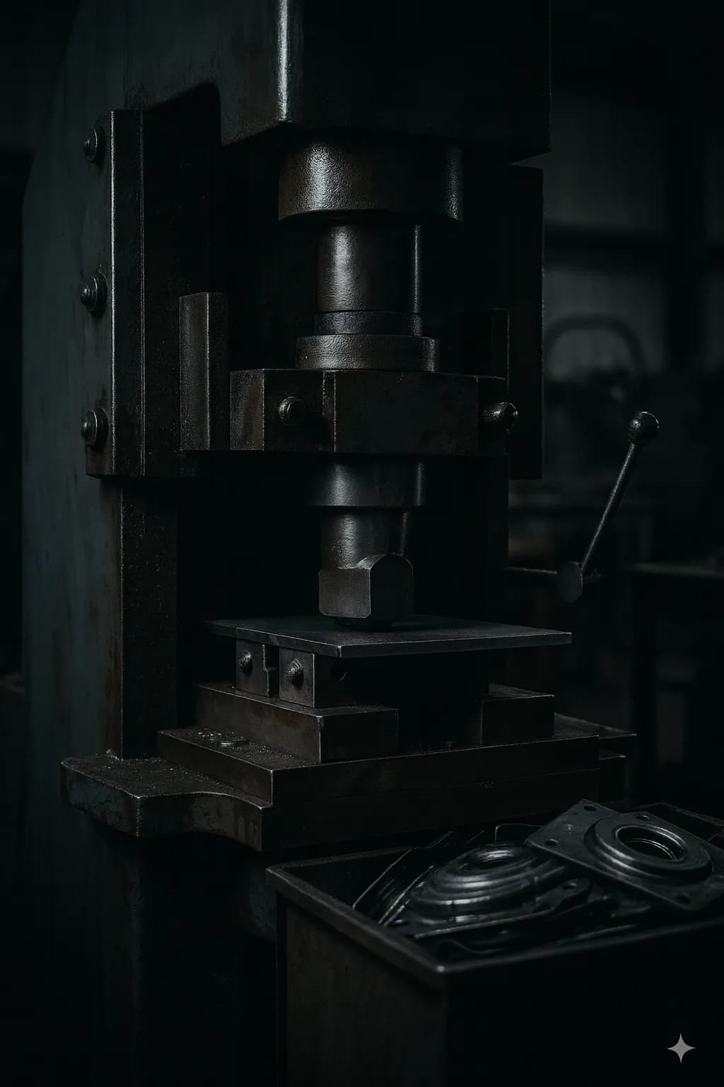
Aero Enterprises converts flat sheet metal into precision components through a controlled sequence of power press stamping, CNC press brake bending, punching, deburring, and powder coating. Each stage is checked before the next one begins so dimensional errors do not carry forward through the production cycle.
Quick Summary
How a Flat Sheet Becomes a Precision Component
Every fabricated part starts as a flat sheet or coil, but the manufacturing path depends on part geometry, material grade, tolerance, and downstream assembly needs. A bracket, enclosure panel, or hardware part may all begin with the same base material but require different process sequences. What matters is deciding the correct route before production starts, not trying to fix mistakes at later stages.
Technical Insight
Most dimensional failures in sheet metal production come from compounding error across stages. A small blanking error can shift bend position, which then moves a hole pattern out of tolerance on the finished part. Catching errors at the first-off stage saves time, material, and rework cost.
Why It Matters
Clients need consistent parts that fit assemblies correctly on the first run. A controlled process reduces rejection rates, rework, and delivery delays.
Stage One: Raw Material Verification
Finished part accuracy starts with the right incoming material. Coils and sheets are checked against Mill Test Certificates for grade, thickness, and mechanical properties before entering production. This matters because thickness variation changes press force, springback during bending, and hole quality during punching.
Stage Two: Power Press Stamping
Power press stamping produces flat blanks, formed details, embossed features, and repeat geometry from sheet or coil. Progressive dies are used where volume justifies tooling investment and where consistent geometry is essential across the entire batch. Compound or single-stage die operations are used where production volume is lower or geometry is simpler.
Stage Three: CNC Press Brake Bending
After blanking or stamping, parts that need flanges, channels, trays, or multi-bend profiles move to CNC bending. The bend sequence is programmed before production so the part remains properly referenced against the back gauge throughout the operation. This improves repeatability and reduces angular variation across batches.
Stage Four: Punching Operations
Punching is used for holes, slots, rectangular cutouts, louvres, and internal profiles where it is more efficient than laser cutting. Punch-to-die clearance is critical because it affects edge quality, burr height, and dimensional control. Tool condition is monitored so worn punches are replaced before burr levels or edge quality become unacceptable.
Stage Five: Deburring and Edge Finishing
Stamped and punched parts carry burrs and sharp edges that can affect handling, assembly, and coating performance. Deburring removes these sharp edges through vibratory or manual processes depending on component size and geometry. Edge breaking also helps powder coat build more evenly on corners and sheared perimeters.
Stage Six: Powder Coating
After fabrication and edge finishing, parts move to the powder coat line for cleaning, pretreatment, coating, and oven curing. A typical industrial powder coating system includes degreasing, phosphate conversion treatment, electrostatic application, and curing. Dry film thickness in the general range of about 60 to 80 microns is widely used for many industrial applications, with checks needed at flats, edges, and bends because coverage is not always uniform.[web:400][web:402][web:403]
How DFM Review Sets the Production Sequence
DFM review is where the manufacturing route is decided before material is processed. It covers material selection, blank optimization, tooling method, bending sequence, punching order, and finish requirement. This prevents avoidable problems such as wrong bend order, distorted holes, or coating failure at unprepared edges.
Market Reality
One of the biggest mistakes in fabrication is assuming that a drawing alone defines how a part should be manufactured. The drawing shows the finished shape, but not the best sequence to get there. Without process planning, even a correct drawing can produce rejected parts.
Good fabrication shops do not just run machines; they decide the correct sequence before the first sheet is cut. That is what improves first-off approval, repeat batch consistency, and on-time delivery.
Contact Aero EnterprisesData & References
Must Read Blogs
How Saddle Pipe Clamps Are Made Using Power Press Stamping
Saddle pipe clamps may look like simple U-shaped parts, but they carry pipe weight, resist vibration, and face moisture and corrosion. Treating them as commodity items bought only on unit price leads to clamps that deform or corrode early. This guide explains how correct die design, material grade, and coating specification extend their service life.
L Patti Manufacturing: How Steel Corner Brackets for Furniture Are Made
An L patti is a small part but a critical structural element in many furniture joints. When thickness, bend angle, and hole accuracy are treated as afterthoughts, brackets deform, joints rack, and warranty returns rise. This guide explains how a correctly specified L patti is designed and manufactured so furniture joints stay square and secure.
Article FAQ
Common questions and technical insights related to From Flat Sheet Metal to Precision Component: How Aero Enterprises Does It.